Second Life UPS Mark II
Table of Contents
1. Introduction
The Secondlife UPS Mark II was envisioned as a successor to the Secondlife UPS Mark I model with the following improvements:
- increased battery capacity
- increased power budget
- circuit simplification
- modularity
- improved load connectors
- various other usability improvements (for example moving the fuses to the front of the enclosure)
- better documentation
The basic premise is to provide a short depth (~250 mm) rack mountable UPS which instead of 230V AC can provide typical low voltages suitable for powering of CCTV cameras, sensors, routers, 802.11 access points, modems, switches, embedded systems (like a Raspberry Pi) and other small devices. This approach is advantegous in terms of saving rack space where a PDU does not have to be mounted as well as potential power efficiency gains of having fewer AC <-> DC power conversion steps.
The UPS design is built using off-the-shelf or recycled components with a few custom made printed circuit boards. Most notably, the UPS is designed to be enclosed using typical 19″ Ethernet switches. These can be obtained very cheap or even given away for free when equipment is discarded. Apart from a reusability solarpunk vibe Ethernet switch enclosures provide us with ready-made cutouts in their front panels. These originally house Ethernet connectors and have typical dimensions. This fact makes it easy to build a modular UPS device with standarised parts.
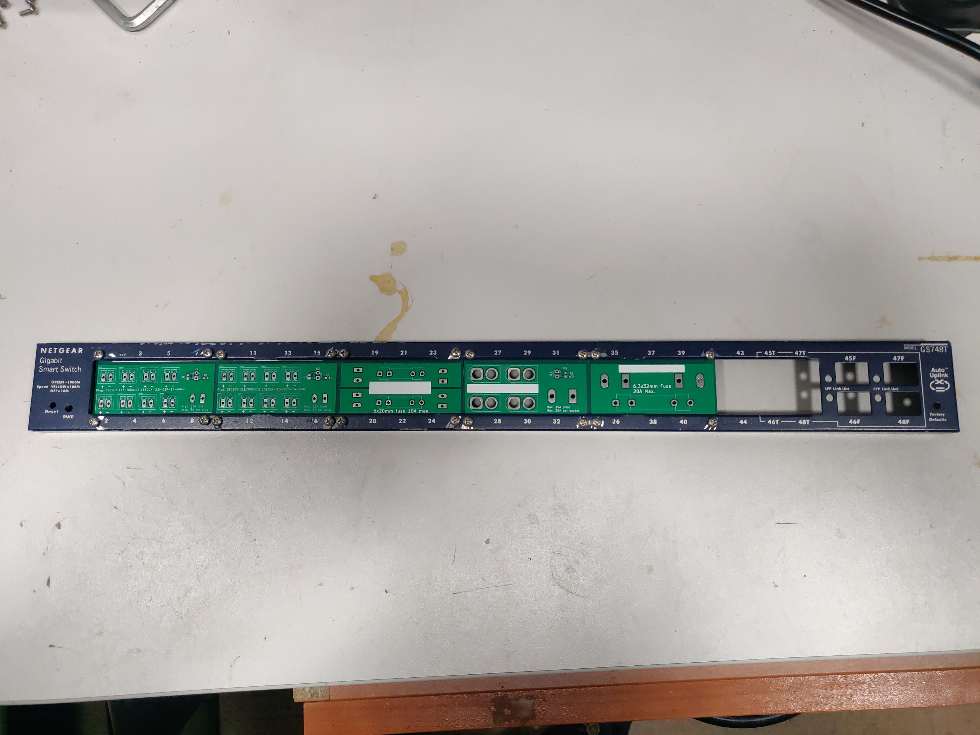
Even though any Ethernet 19″ rack switch enclosure can be used for this build, this particular UPS is going to be housed in an enclosure from a damaged Netgear GS748T switch.
The UPS design is focused around two buses providing standard 12V and 5V voltages using buck converters as well as a "direct" bus (labeled later as Vrail) which is connected directly to the battery or AC power supply. The peculiarity of this bus is that the voltage on it has a significant swing - from 11.2V when operating on an almost depleted battery towards 24V when operating on AC power. The advantage of using Vrail is that its current capacity is not limited by the DC-DC buck converters and can power more power-hungry equipment - for example a Netgear RN3138 NAS.
1.0.1. More battery capacity
In order to provide more power as well as longer runtime, the UPS will contain a 4S24P Lithium-Ion battery pack built from refurbished 18650 cells having a capacity of around 600 Wh (if 2000 mAh cells are used).
1.0.2. More power
After Secondlife UPS Mark I has been deployed there have been a number of changes and additions to my home infrastructure equipment rack. Power requirements have increased. In order to come up with more detailed power requirements for each voltage I measured the amount of current draw during normal operation for each piece of equipment and came up with the following calculations for the power budget requirements of the UPS. As the voltage on the Vrail bus is not constant and changes from 11.2V when operating on a discharged battery and 24V when operating on AC its more useful to specify it's performance in terms of power not current.
| Device | 12V Current [A] (measured) | 12V Current [A] (max) | 5V Current [A] (max) | Vrail power [W] (measured) | Vrail power [W] (max) | Notes |
|---|---|---|---|---|---|---|
| Router | 5 | Axiomtek NA342 | ||||
| GPON Modem | 0.5 | HALNY HL-1GE | ||||
| Core Ethernet switch | 1.33 | 4 | ||||
| Planet GSD-800S switch | 21 | PoE injected | ||||
| Ubiquity Unify AC Lite AP | 0.16 | 0.54 | Via boost converter and PoE injected, rated at 6.5 W (see datasheet), passive 24V PoE Mode B (230V/0.02A) | |||
| Raspberry Pi | 2.1 | |||||
| Gate magnetic lock | 0.25 | |||||
| Network Attached Storage | 40 | 100 | Built-in ATX power supply is 180W but real power draw has not exceeded 100W | |||
| Network Video Recorder | 40 | Boost converter to 48V | ||||
| Security Cameras (total) | 0.75 | |||||
| Miscelaneous (ie. rack fan) | 0.5 | 0.5 | ||||
| Total | 2.49 | 10.54 | 2.6 | 40 | 161 |
1.0.3. Capacity planning for power buses
We take into account an efficiency of 0.8 for the buck converters and assume that the lowest battery voltage will be 11.2V which corresponds to the BMS cutoff voltage of 2.8V per cell (11.2V = 3 * 2.8V).
| Bus | Voltage [V] | Max current [A] | Max power [W] | Vrail load on batt power [A] | Vrail load on AC power [A] |
|---|---|---|---|---|---|
| 12 V | 12 | 10.54 | 126.48 | 14.116071 | 5.02 |
| 5 V | 5 | 2.6 | 13. | 1.4508929 | 0.4375 |
| Direct | 161 | 14.375 | 6.7083333 | ||
| Total | 300.48 | 29.941964 | 12.165833 |
All of the above calculations allow us to select:
- internal wiring cross-section (AWG)
- internal and external connector types
- fuses
- buck converters maximum power and current
- AC power supply maximum power and current
An AC power supply with at least 300W is needed to power the loads with some room needed to charge the battery. For this reason a 400W power supply has been selected (see summary in BOM).
1.0.4. Solid-state operation
Instead of the previously used relay-based power path switching scheme a solid-state power switch (KiCad files) based on MOSFETs driven by the LTC4416 PowerPath controller will be used.

1.0.5. Modularity
One disadvantage of the previous Secondlife UPS design was the fact that the front connectors where loads can be powered were placed on hand-made breadboard PCBs. After some thought I have decided that this approach makes the design hard to replicate and adapt. To improve this I designed a number of standard sized PCBs that host common load connectors and fuse sockets. All of the PCBs fit into cutouts in Ethernet switch enclosures hosting 4x2 Ethernet ports. This is the most common cutout size in an Ethernet switch and it allows a user to mix and match modules based on their needs. Currently the available modules include:
- a fanout with 8 x DEGSON 13EDGVC-3.5 pluggable load connectors with a power indicator LED, this module is designed to power low-power loads (KiCad files)
- a fanout with 6 x XT-60 pluggable load connectors with a power indicator LED, this module is designed to power high-power loads (KiCad files)
- a fuse module containing two fuse sockets accepting typical 5x20mm glass fuses (KiCad files)
- a fuse module containing one fuse socket accepting a 6.3mmx32mm glass fuse (KiCad files)
All of these modules share a common mechanical design and can be used to build many types of front panel layouts. If the project is successful I'm planning to design other modules such as a PoE injector or a battery SoC (State of Charge) indicator module. Another future improvement idea is a 3D-printable drilling guide which will help with precision while drilling mounting holes in the enclosure.
As an example in the Secondlife UPS described in this document the following modules are mounted on a long (48 port) cutout in the enclosure:
- one fanout with 8 x DEGSON 13EDGVC-3.5 pluggable load connectors module powered by the 5V bus
- one fanout with 8 x DEGSON 13EDGVC-3.5 pluggable load connectors module powered by the 12V bus
- one fuse module containing two fuse sockets accepting typical 5x20mm glass fuses protecting the 12V and 5V buses
- one fanout with 6 x XT-60 pluggable load connectors module powered by the Vrail bus
- one fuse module containing one fuse socket accepting a 6.3mmx32mm glass fuse protecting the Vrail bus
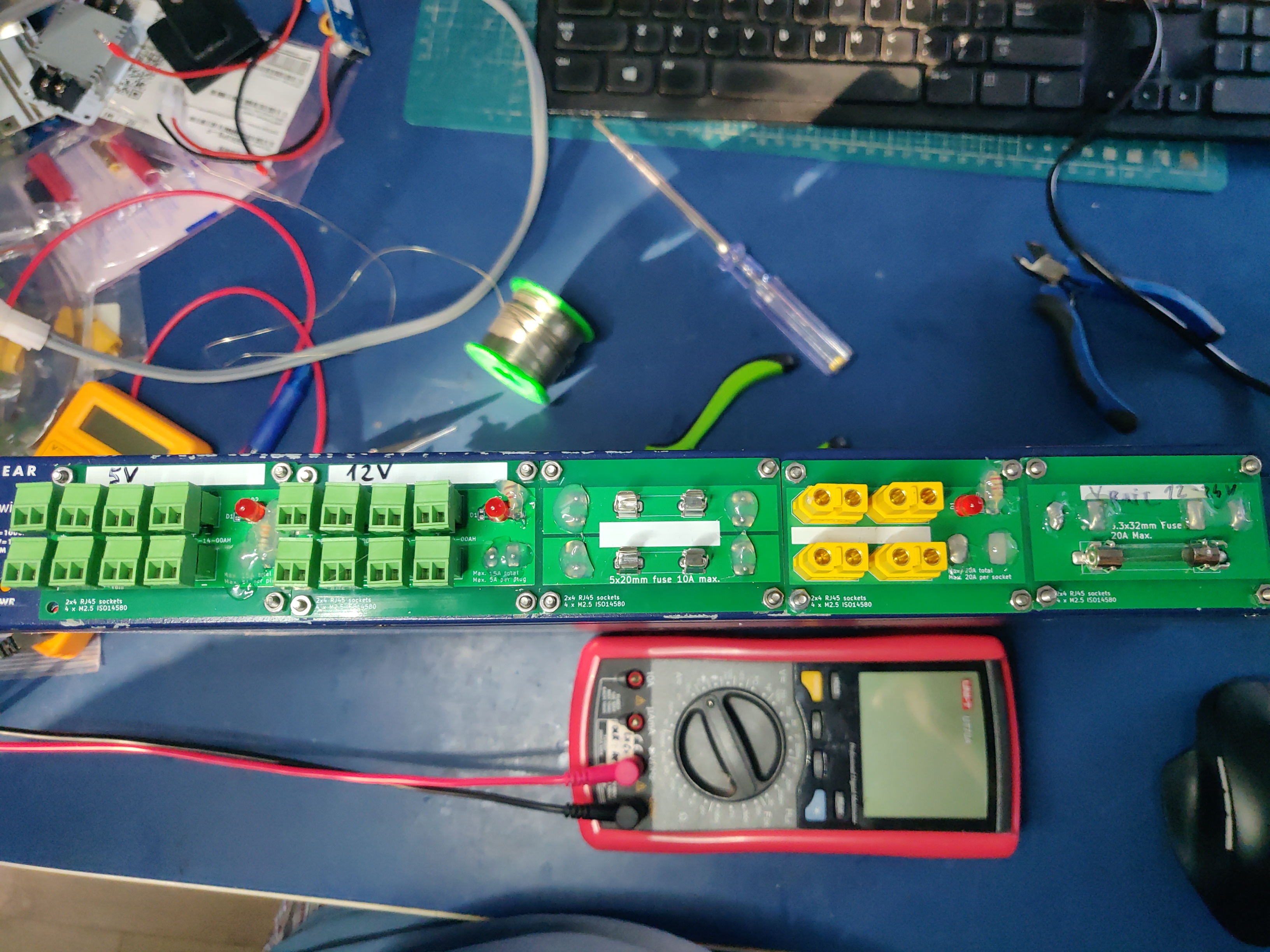
The exposed through-hole component leads have been covered with hot glue. In the future dedicated 3D-printable plastic covers might be introduced for each specific module which can be screwed on to improve the aesthetics.
2. Overall schematics
The overall schematics of the UPS. Some modules (for example the ideal diode circuit or the BMS) are drawn on a conceptual level only.

3. Build instructions
3.1. Planning
As the initial step all of the parts need to be placed in the enclosure to check if everything will fit, plan overall wiring and airflow.
Please note, that the cells should be placed in the cell holders or mock cells need to be used to plan the layout.
3.2. Enclosure preparation
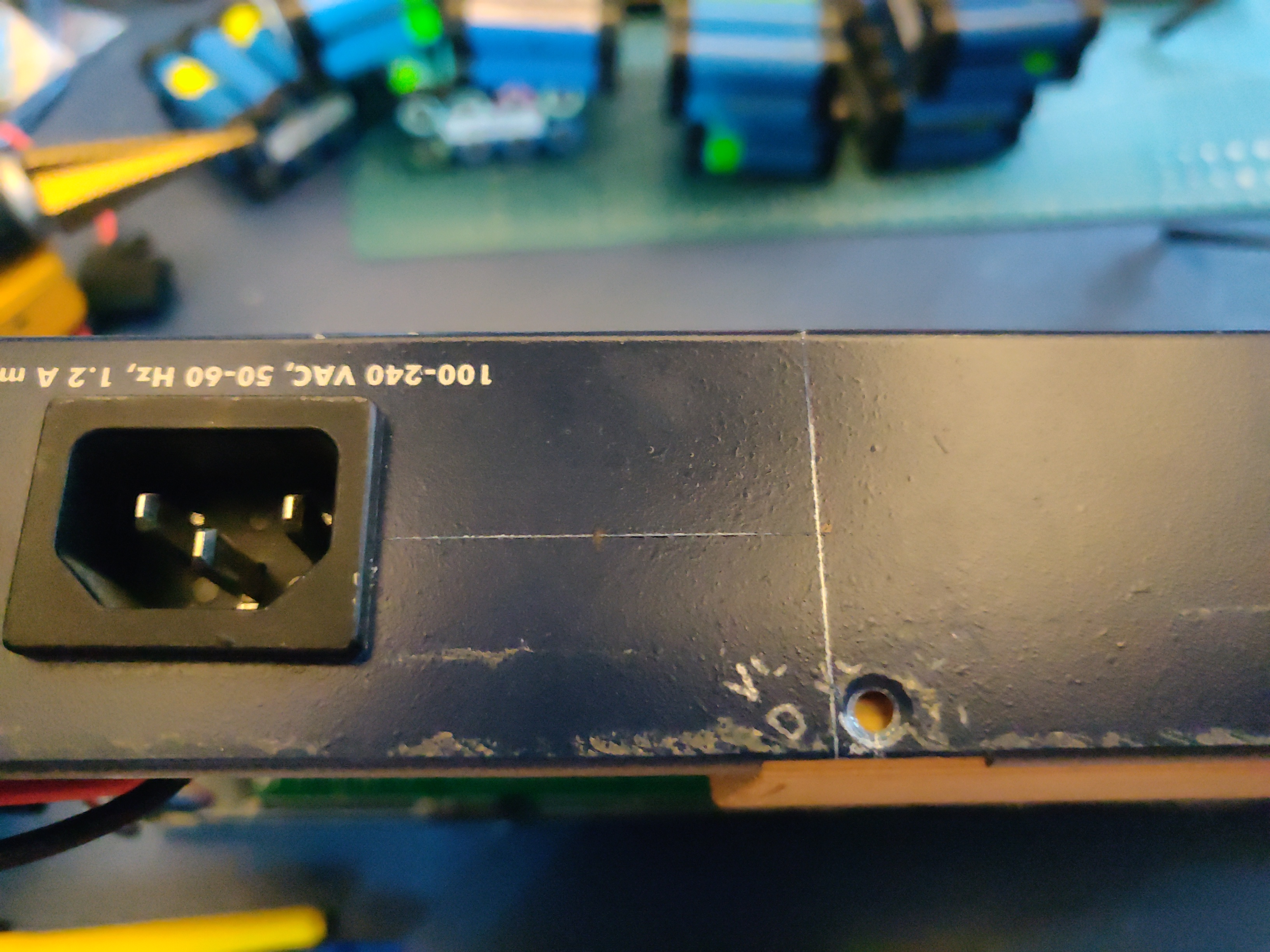
The steps below describe the preparation of an empty 19″ 1U enclosure for placement of UPS submodules. Most internal components from the device that you are reusing should be removed, some like AC sockets, grounding lugs or fans can be left in the case.
3.2.1. Stud removal
After placing the batteries, AC power supply, DC-DC converters, BMS and other components some studs will need to be removed:
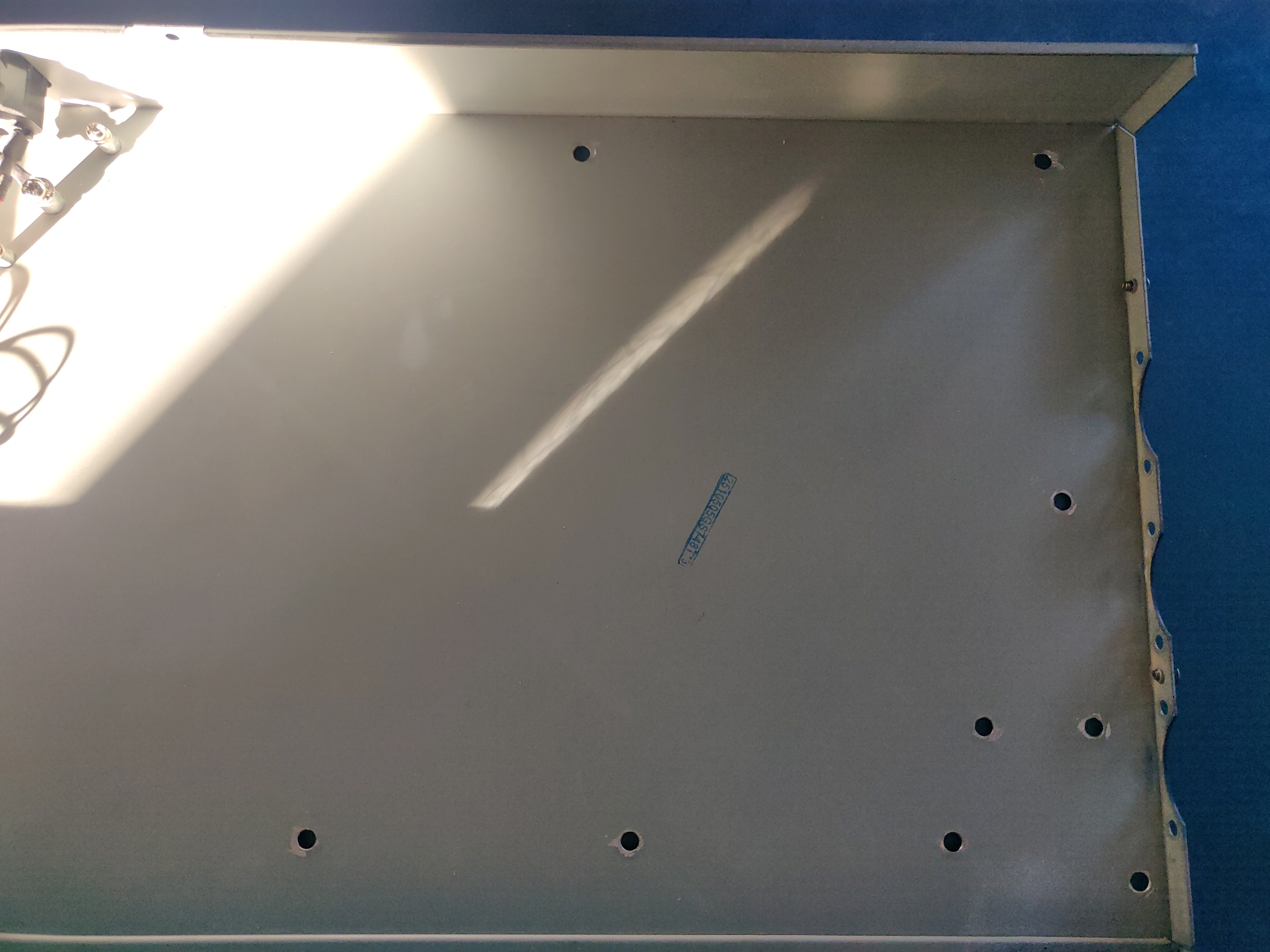
Some notes on the process:
- Thoroughly deburr the corners of the drilled holes with a deburring tool or a Dremel. Leftover burrs can damage 18650 cell insulation sleeves and cause a short.
- Drill with a 5mm metal drill
- Drill from the bottom of the case
- Use a puncturing tool for easier drilling. A cheap one can be bought for 2-3 EUR.
- Support the chassis with 40mmx40mm wood cubes to prevent bending
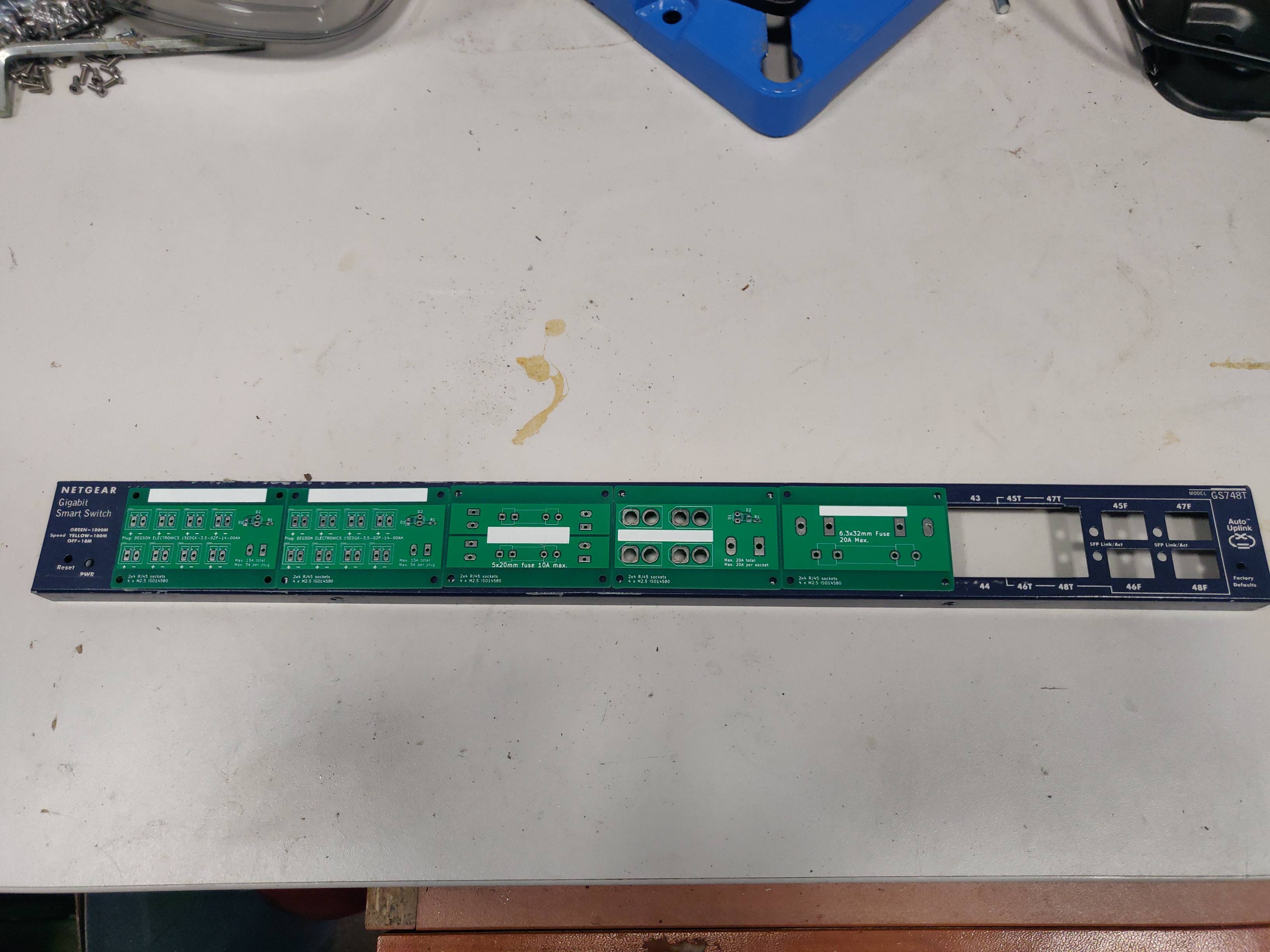
3.3. Front panel assembly
As described before the front panel is built up out of modular PCBs screwed to the front of the enclosure with screws and nuts.
The module PCBs have M2.5 screw holes drilled and in my case I used M2.5 x 8mm screws, washers and nuts to attach the modules. Each module covers the space of 4x2 RJ45 ports which is a typical cutout size for Ethernet switches.
Plan your layout first taking into consideration the routing of internal wires and other components like the power supply and batteries which can be pretty big. Plan for some clearance between elements.
Usually the front of the enclosure can be detached from the rest of the case and this should be done first.
Tools needed for attaching the modules to the enclosure front:
- drill press (optimal)
- hand drill (usable)
- a 3mm metal drill
- dremel or deburring tool
- hole punch
- sharp pen for hole marking
The module PCBs can be placed inside or outside the front panel assembly depending on how the front panel latches onto the rest of the enclosure.

In my case the PCBs needed to be mounted outside with screws pointing outwards in order for the enclosure front to fit the rest of the case. Test the entire assembly process in order to be confident that there will be no problems later.
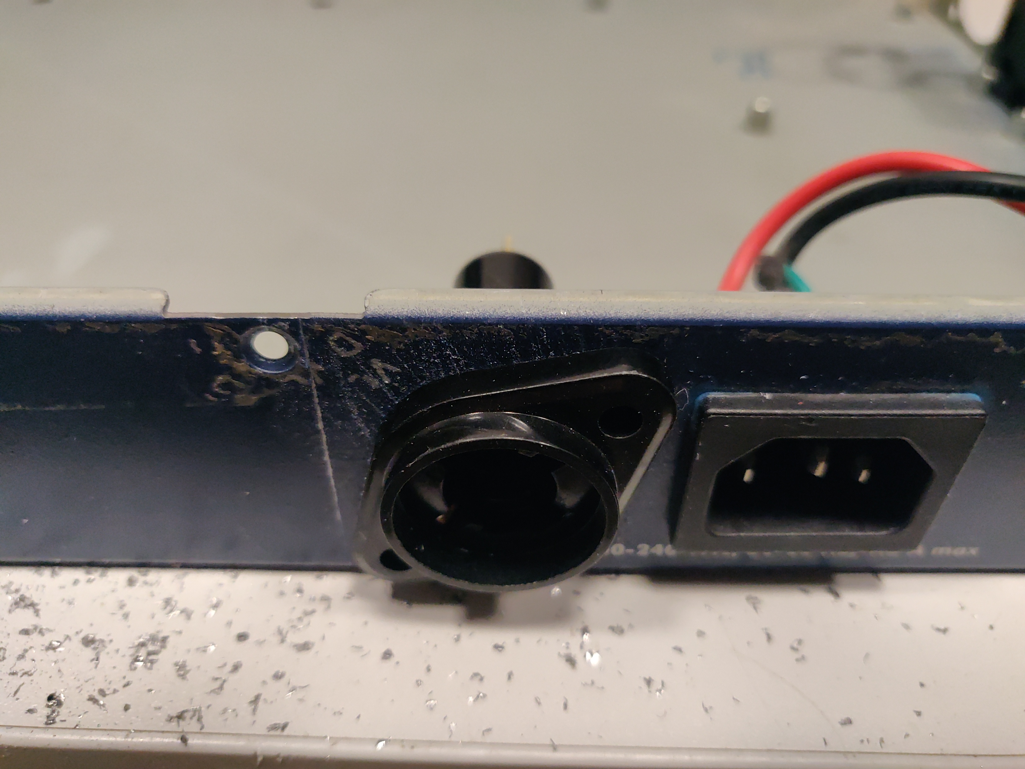
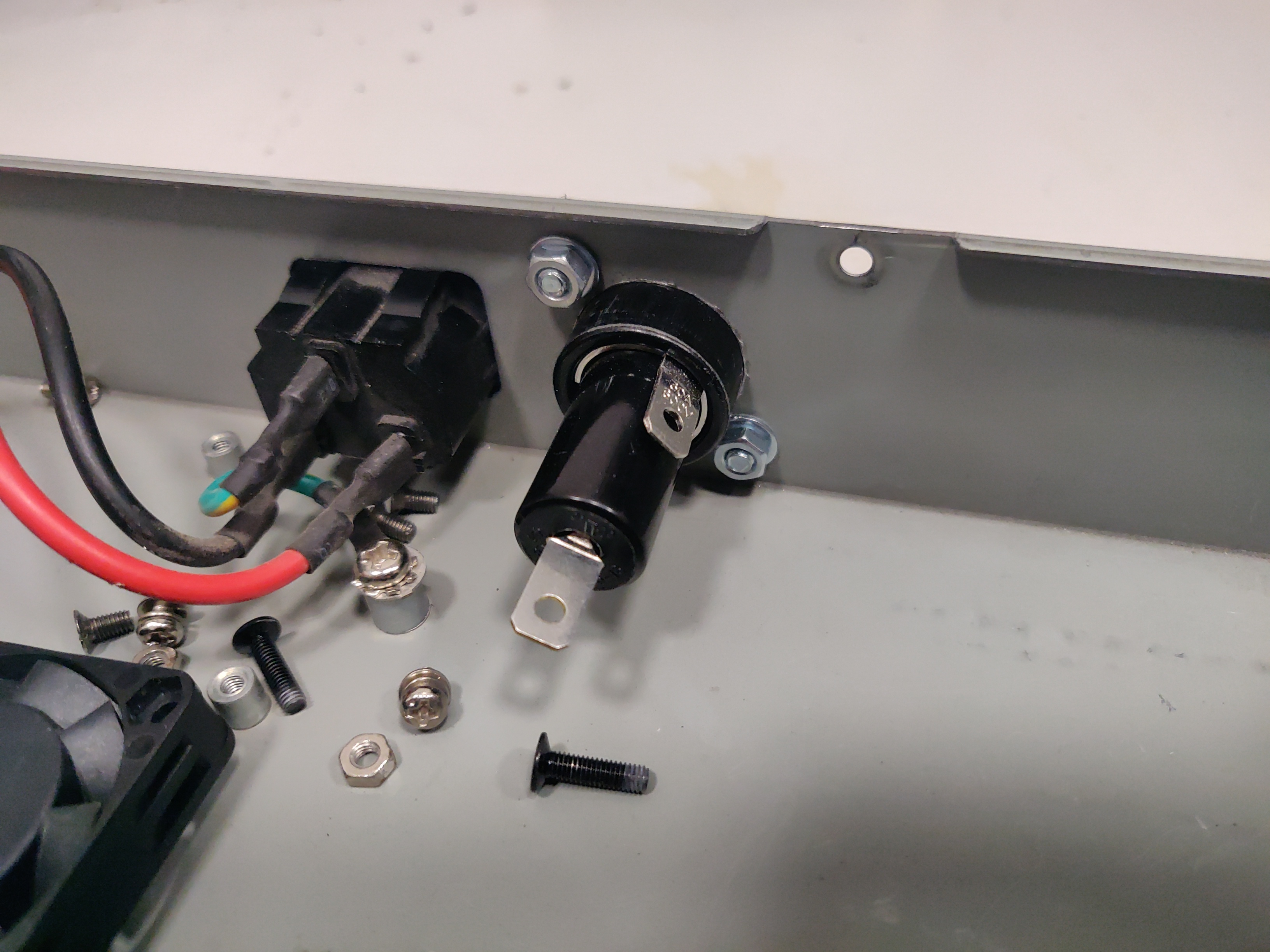
3.3.1. Mounting the main battery fuse
The main battery fuse socket should be selected to handle the battery current and be easily mountable in the enclosure. The most practical sockets are those that can be mounted with just round holes. The fuse selected needs to be a DC fuse rated for the voltage that the battery operates on. Those types of fuses can be often found distributed under the "solar" or PV categories. The fuse that I used in my build is linked in the BOM at the end. As the fuse socket is pretty large, care needs to be taken to drill the main mounting hole exactly on the center of the back plane.
In my socket, M4 screws were used for mounting, 22mm hole was drilled with a step drill. Remember about lubricant, my Metabo BS 12 BL Q 20 Nm cordless drill was struggling a bit but you can do it with some patience.
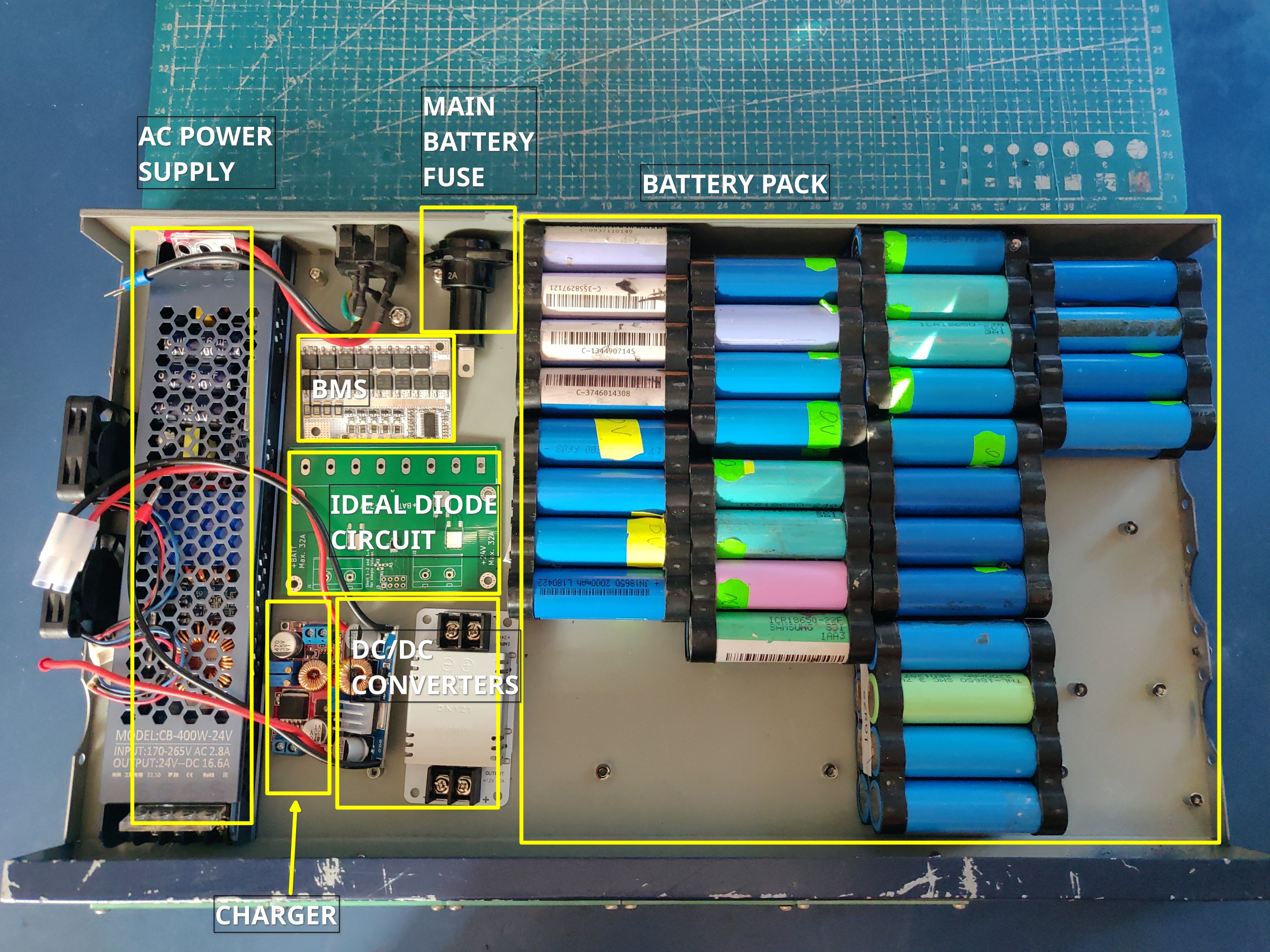
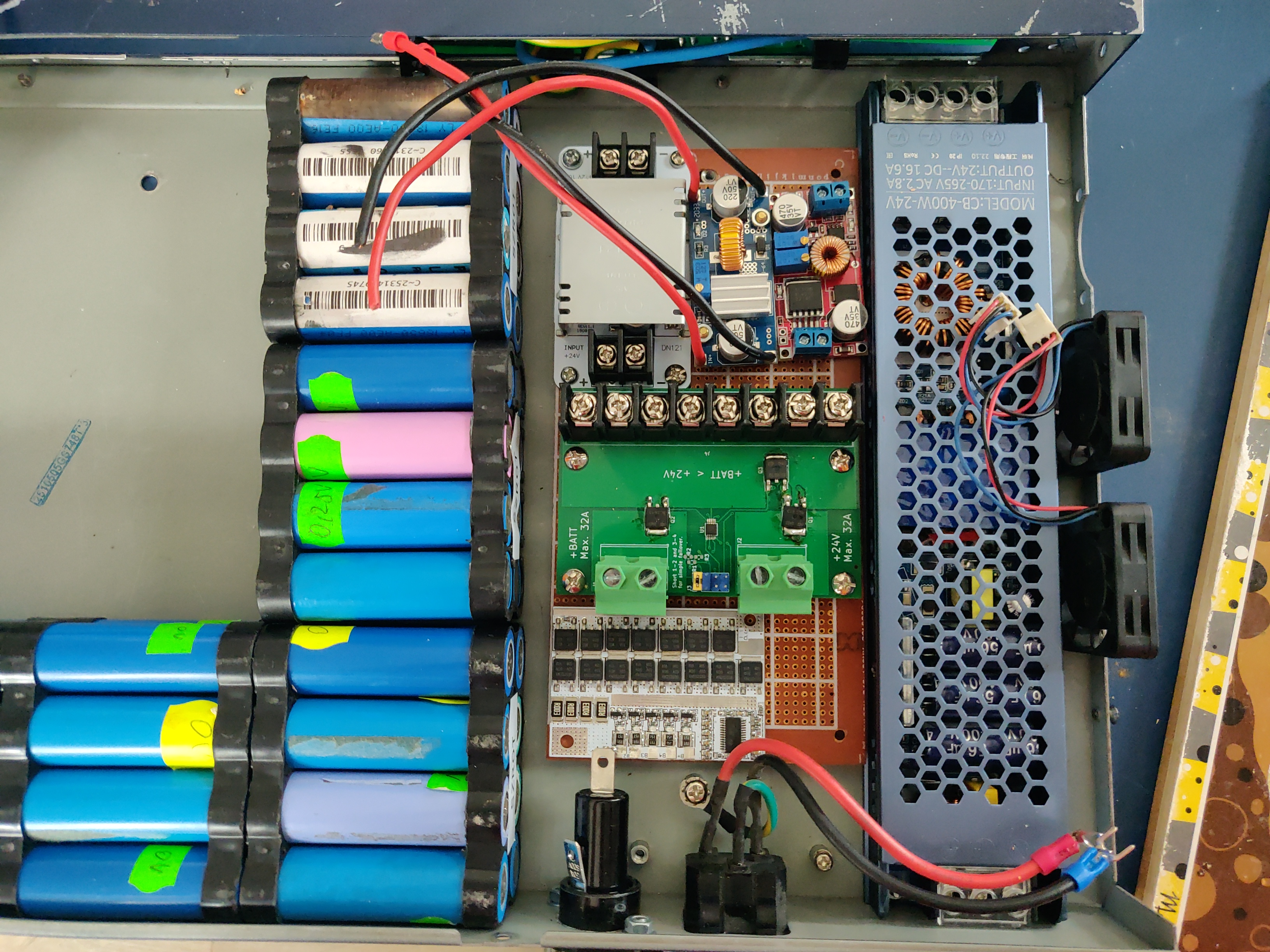
3.4. Circuit assembly
The BMS, ideal diode circuit and DC-DC converters are mounted on a baseplate made from a prototype PCB using some of the leftover studs in the enclosure:
All of the other modules can be then mounted either with either screws or doublesided tape:
3.5. Battery assembly
3.5.1. Battery cell selection
The 18650 cells used for the making of the battery pack can be new or refurbished from e-bike, cordless tools, old laptop batteries or other sources. Consult more specialised forums like Secondlife storage for tips on selecting, obtaining and testing reused 18650 cells. Two critical points to keep in mind are:
- always check the specifications for the cells you are using (find and read datasheets) so as not to exceed current or voltage limits
- measure and match the discharge capacity and internal resistance of the cells in a battery pack to be as close as possible
3.5.2. Nickel strip thickness calculations
The battery will be built by welding nickel strips onto the cells in a certain pattern. The basis of the calculation of the required width of the nickel strips is the following table. Unfortunately the exact methodology of how these numbers have been obtained is unclear but it's the best data I have found so far:
| Strip size | Optimal [A] | Acceptable [A] | Poor [A] |
|---|---|---|---|
| 0.1mm x 5mm | < 2.1 | 3.0 | > 4.2 |
| 0.1mm x 7mm | < 3.0 | 4.5 | > 6.0 |
| 0.15mm x 7mm | < 4.7 | 7.0 | > 9.4 |
| 0.2mm x 7mm | < 6.4 | 9.6 | > 12.8 |
| 0.3mm x 7mm | < 10.0 | 15 | > 20.0 |
As previously calculated, the maximum battery current will be around 30A during discharge therefore the current collectors at the battery terminals need to use two 0.3mm strips. Additionally, the strips that I am using are 8mm wide not 7mm wide giving some headroom for current capacity.
3.5.3. Welding the cells
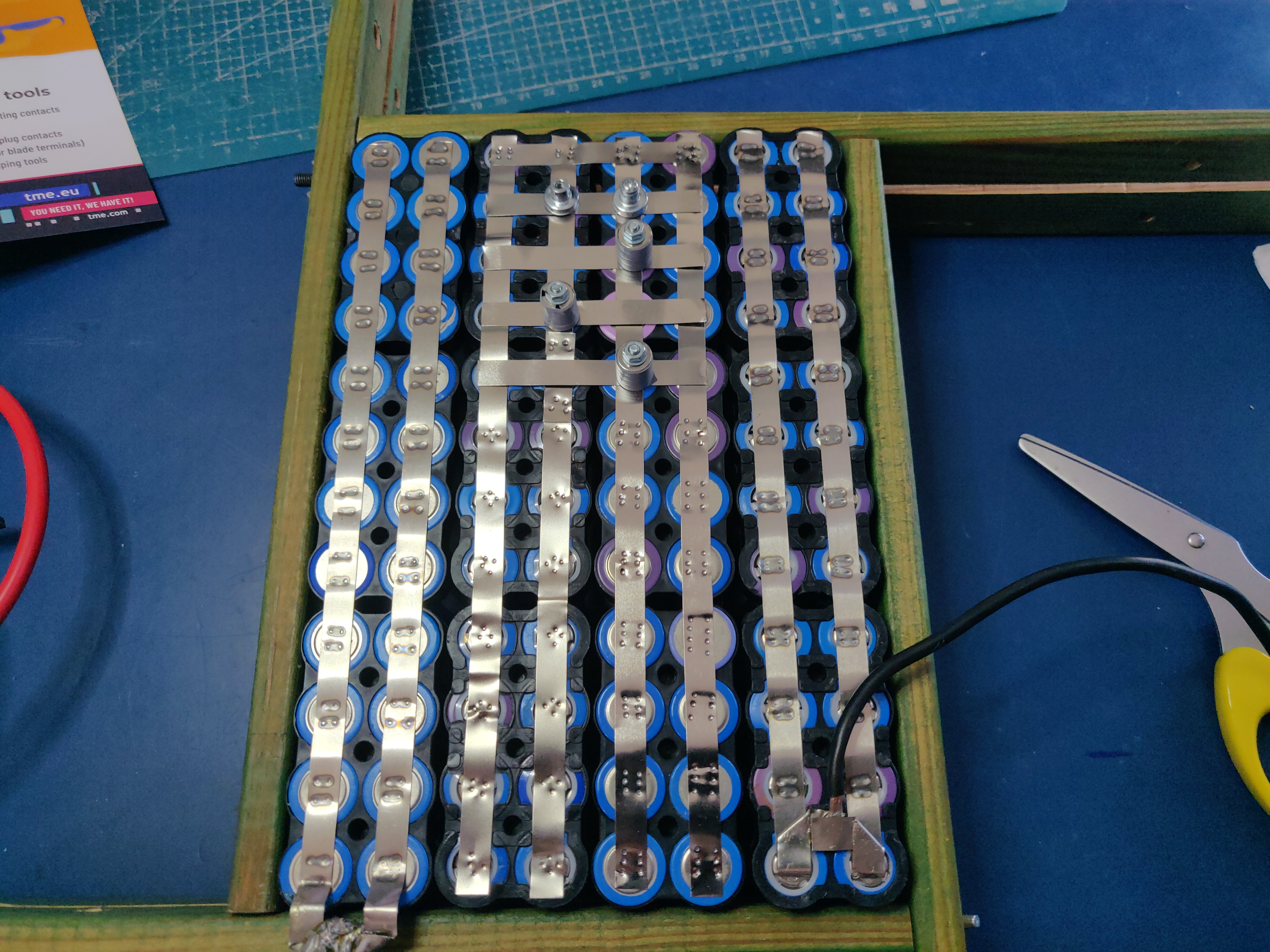
The general approach is to connect the cells together with 8mm wide nickel strips using spot welding. In order to facilitate cell voltage verification and equalization within each of the 24P blocks first only one side of the block (the positive cell terminals in my case) is welded first, then cells charge is equalized and then the second cell terminals (negative cell terminals in my case) are welded together. Most welds are performed with 0.1mm and 0.12mm nickel strips but the terminal connections for the entire battery are built out of 0.3mm strips for designed current capacity.
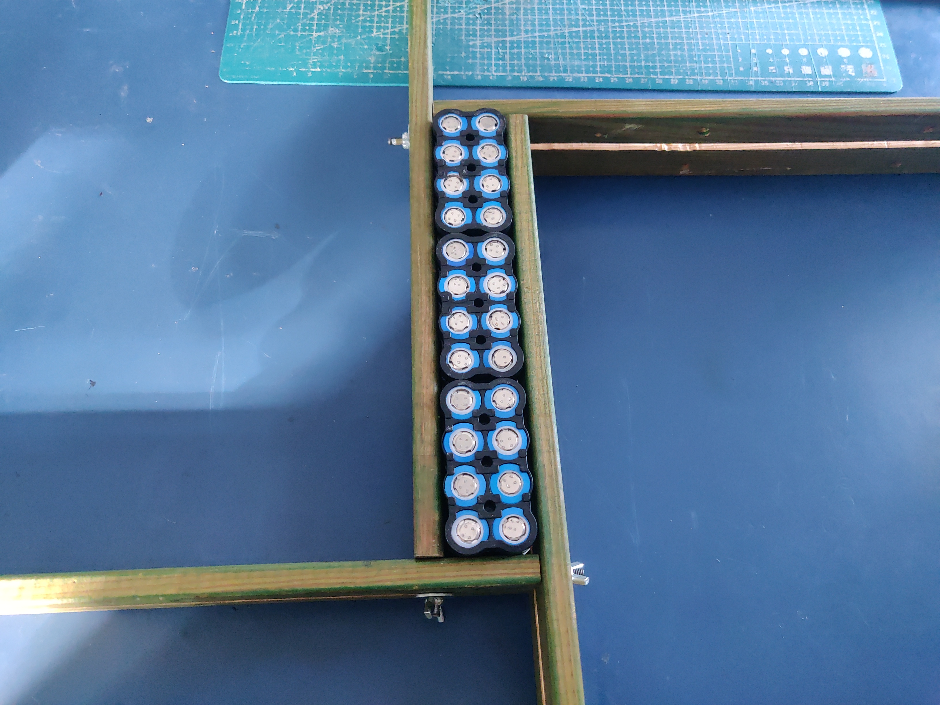
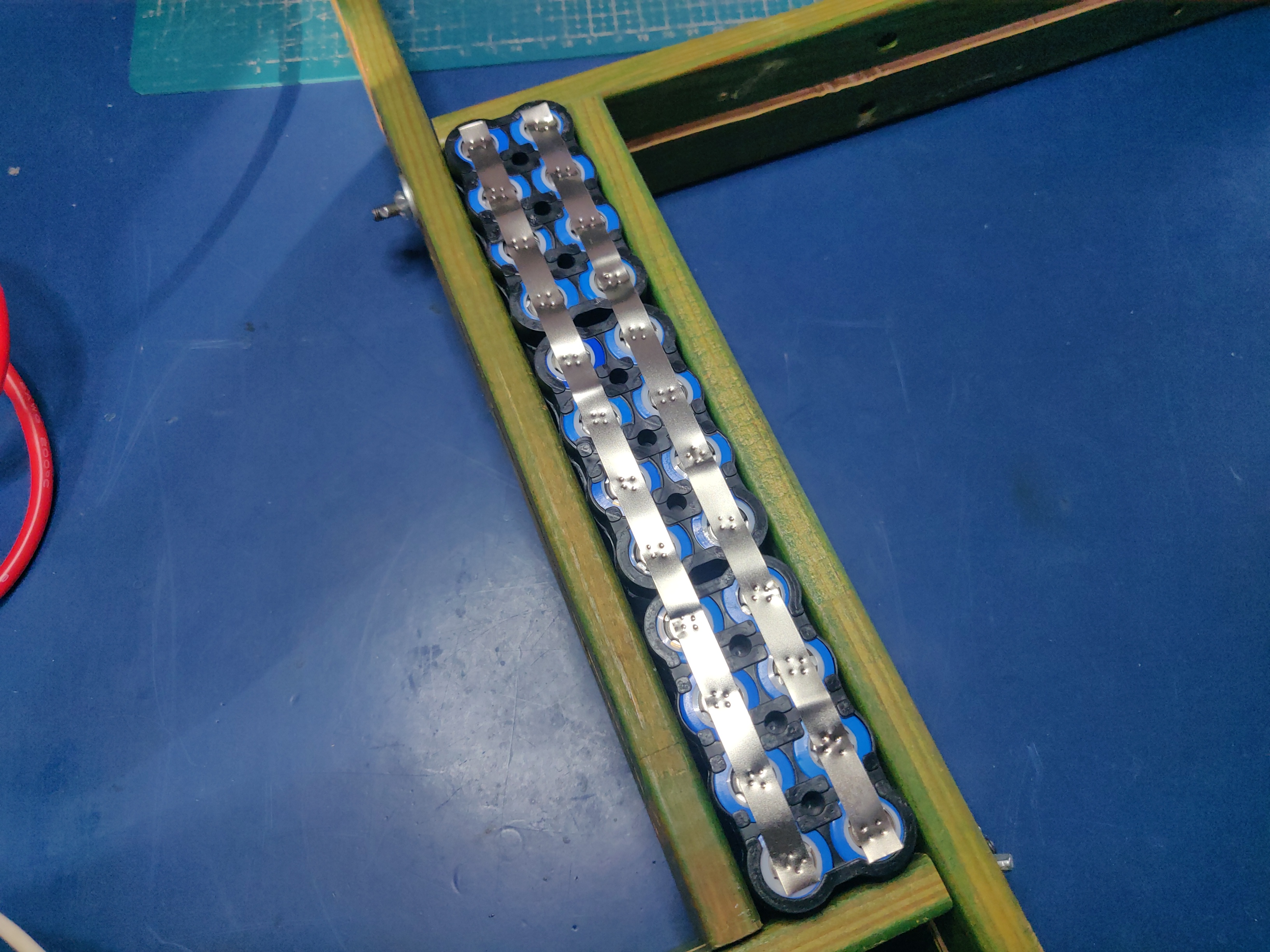
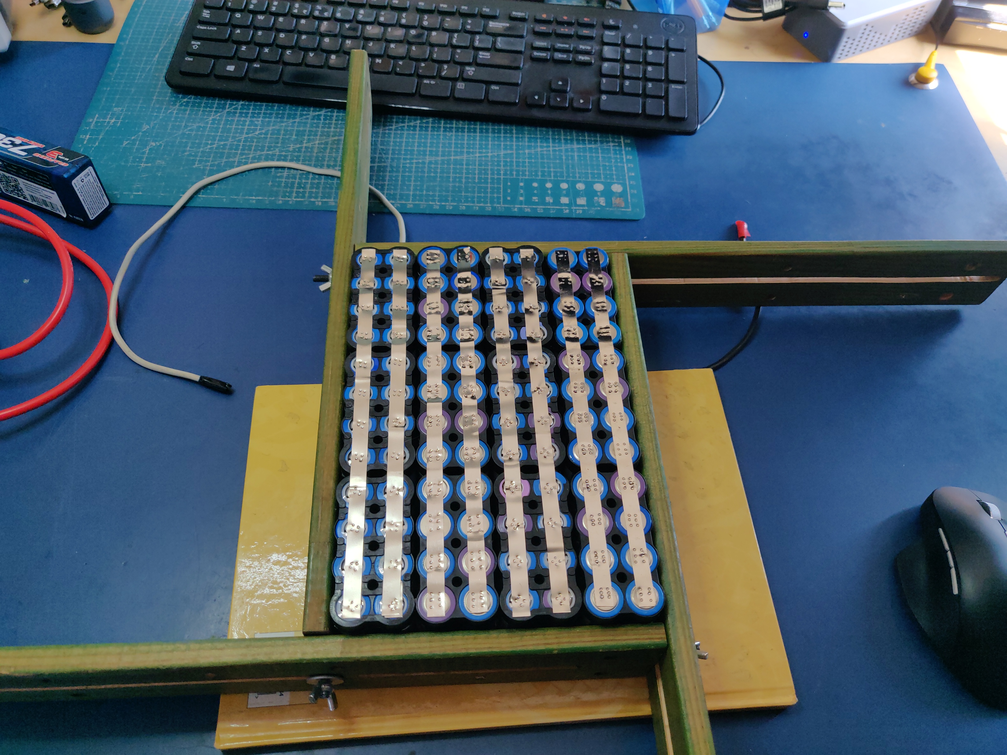
A welding jig is used to keep the cells in place during welding. Such a jig can be purchased or manufactured by yourself as it's simply a set of four pieces of wood with a long slot cut alongside their length. The design for such a jig can be found below:

The cells for each of the four 24P blocks are inserted into 4x2 cell holders refurbished from old "hoverboard" battery packs and aligned using the jig. This is recommended as the welded nickel strips cannot be used as the only mechanical support for the cells:
Nickel strips are secured to the cells using small neodymium magnets to not move during the welding process:
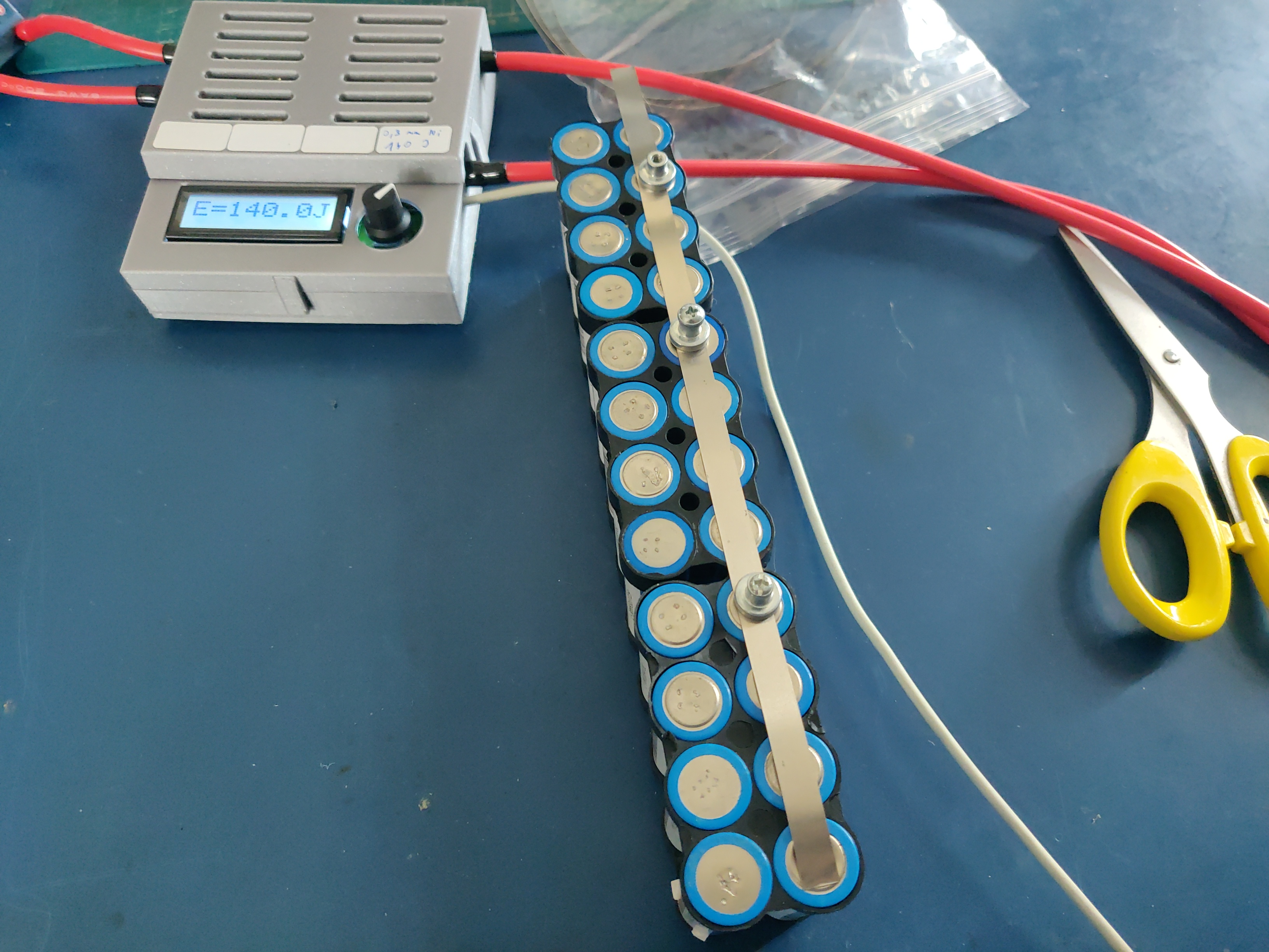
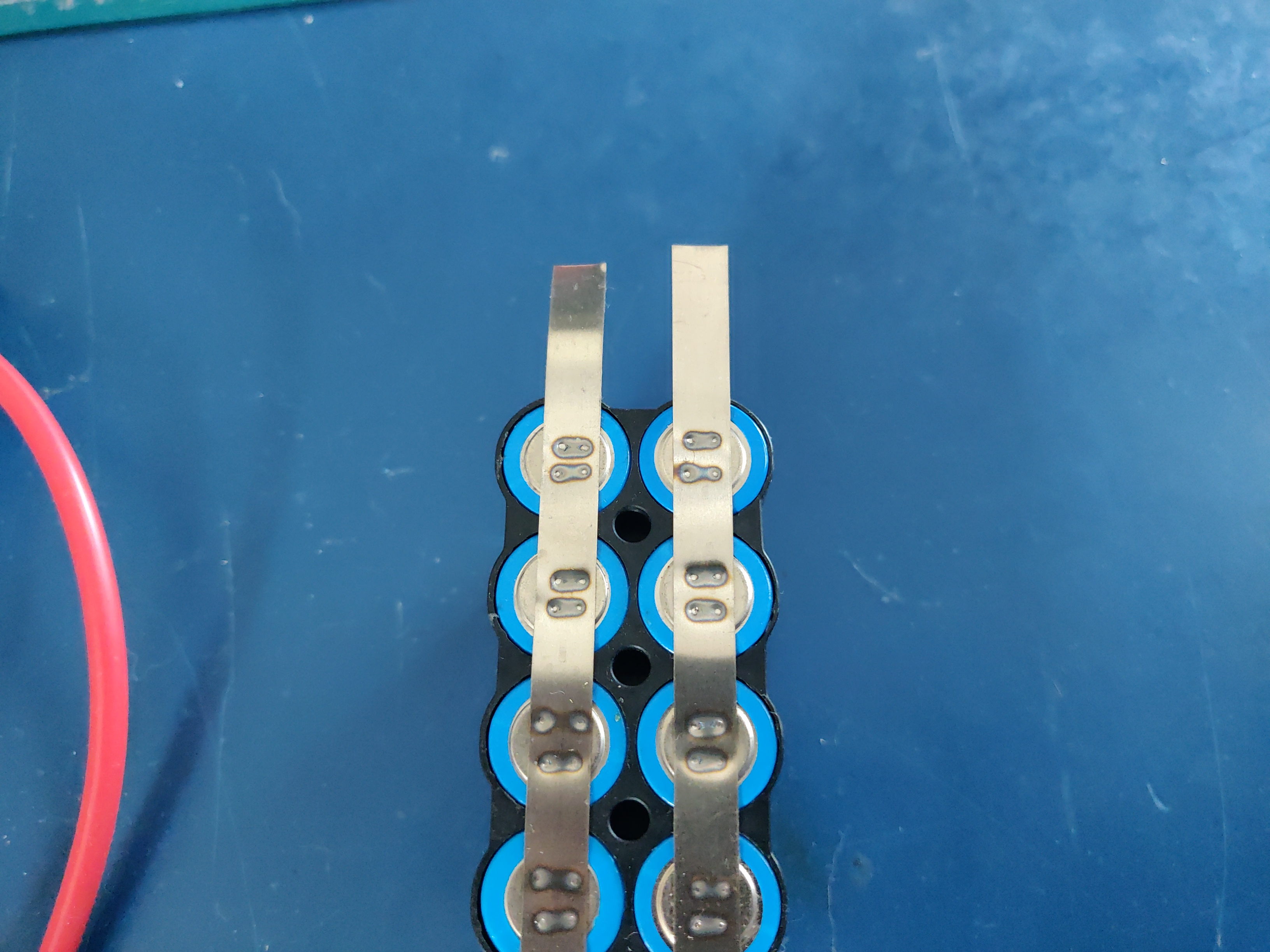
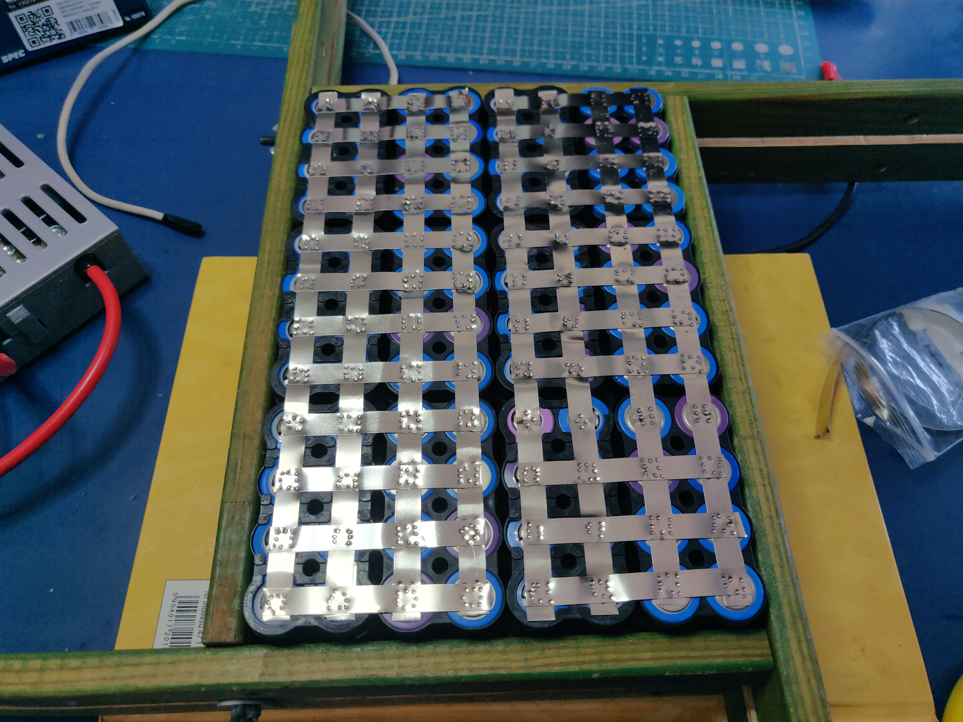
The strips are welded to the cells using a kWeld from Keenlab spot welder powered by a HV Stock Spec GRAPHENE-3 7300mAh Hardcase battery - 7.6V LiPo - 130C/65C. The effect of welding both 0.1mm and 0.12mm thickness strips that connect the cells can be seen below:
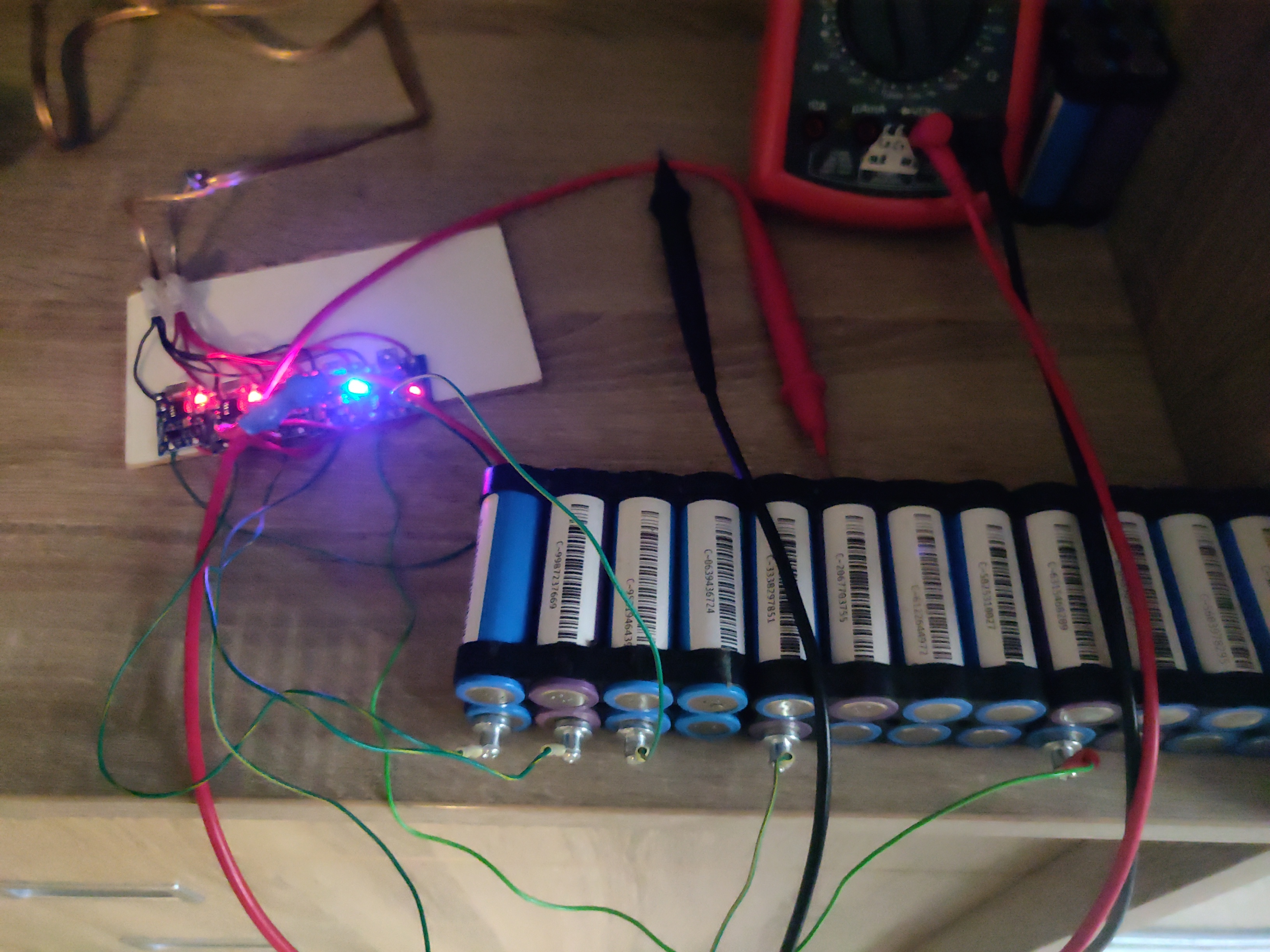
The cells in all four 24P blocks are first checked with a voltmeter and if some of them have self-discharged below 4V they are charged individually. I use a DIY "charger" which connects together 5 cheap "Li-Ion charger" modules based around the popular TP4056 chip.
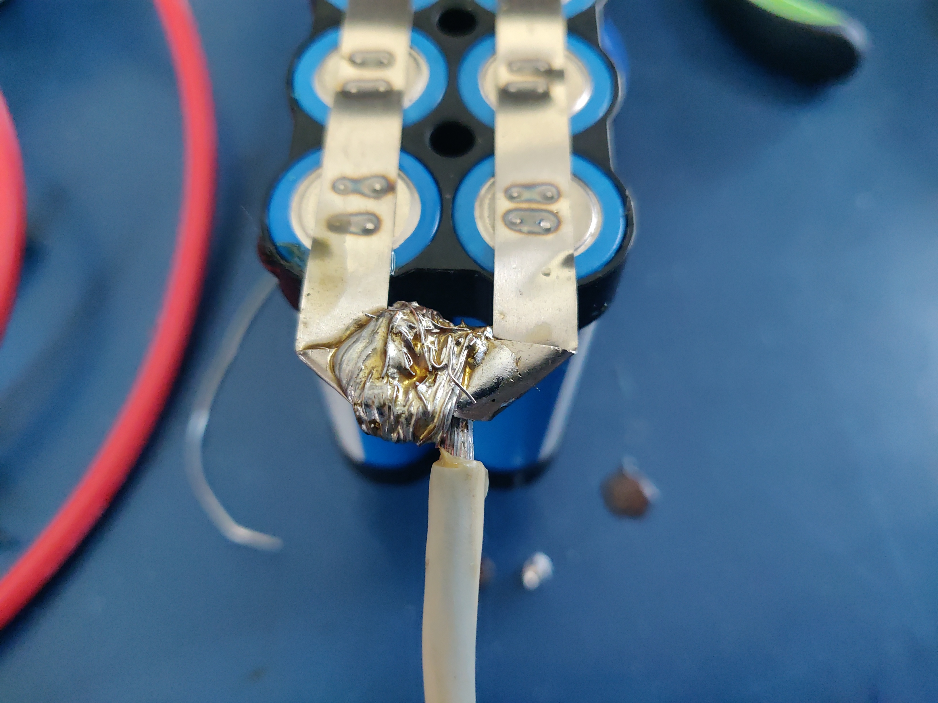
The strips used for terminal current collectors (providing the positive and negative for the entire battery) are longer than the length of the block to be bent together and soldered to 4mm² wires.
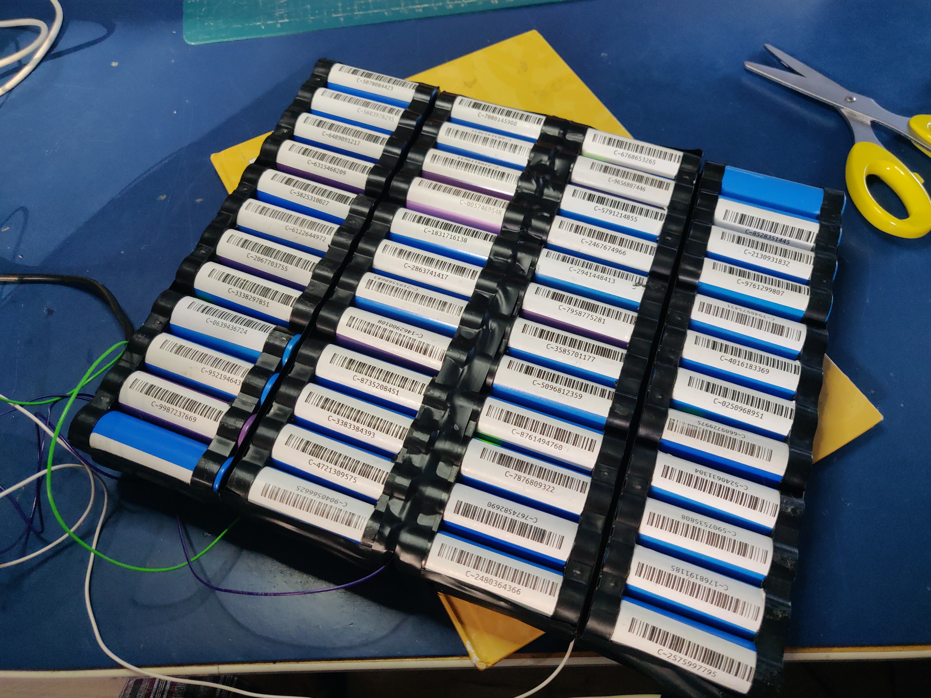
After all blocks are welded and equalized they are aligned side-by-side in the welding jig and connected with more 0.1mm/0.12mm strips. This process can be seen below. Care needs to be taken at this stage in order to properly orient the blocks taking into account the polarity as well as final wiring in the enclosure. A quick photo summary of these steps can be found below:
Additional tips on the cell welding process are:
- take some old cells and practice welding settings and technique with different nickel strip thickness before starting to weld the battery
- as a rule of thumb for a proper weld, when you pull off the strip from the cell there should be a hold left in the strip, in other words the weld should be stronger than the nickel strip itself
- keep the cells and nickel strip clean (degrease with isopropyl alcohol if required) and use work cotton gloves during assembly
- for best results use pure nickel strips, some places sell nickel plated steel strips which are cheaper but have more resistance
3.5.4. Attaching voltage sense wires
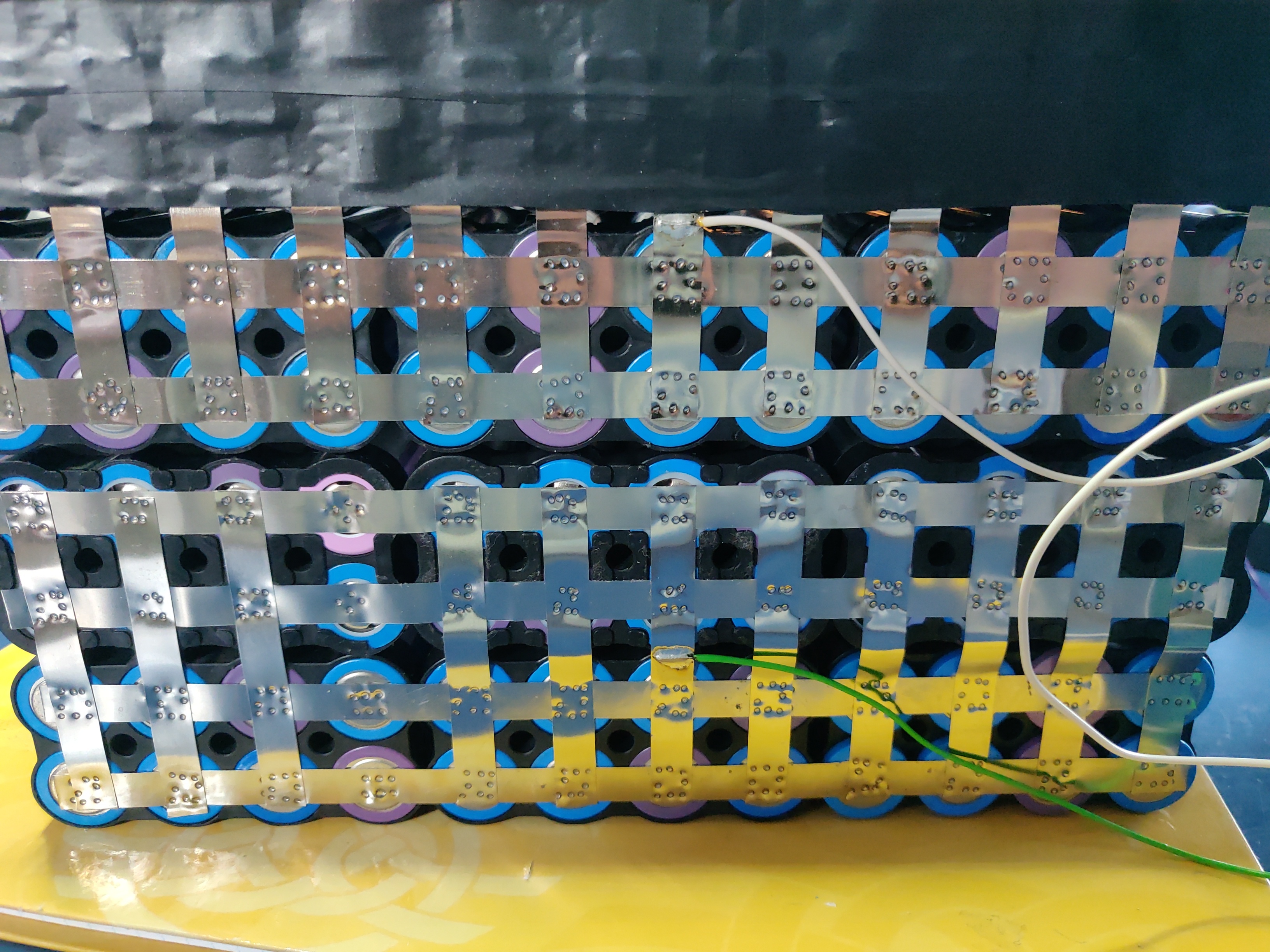
The voltage sense wires are soldered to allow the BMS to measure the voltage for each 24P block and react accordingly when voltage limits are reached:
3.5.5. Final assembly
The final assembly involves isolating and securing all exposed nickel strips and wires with electrical tape:
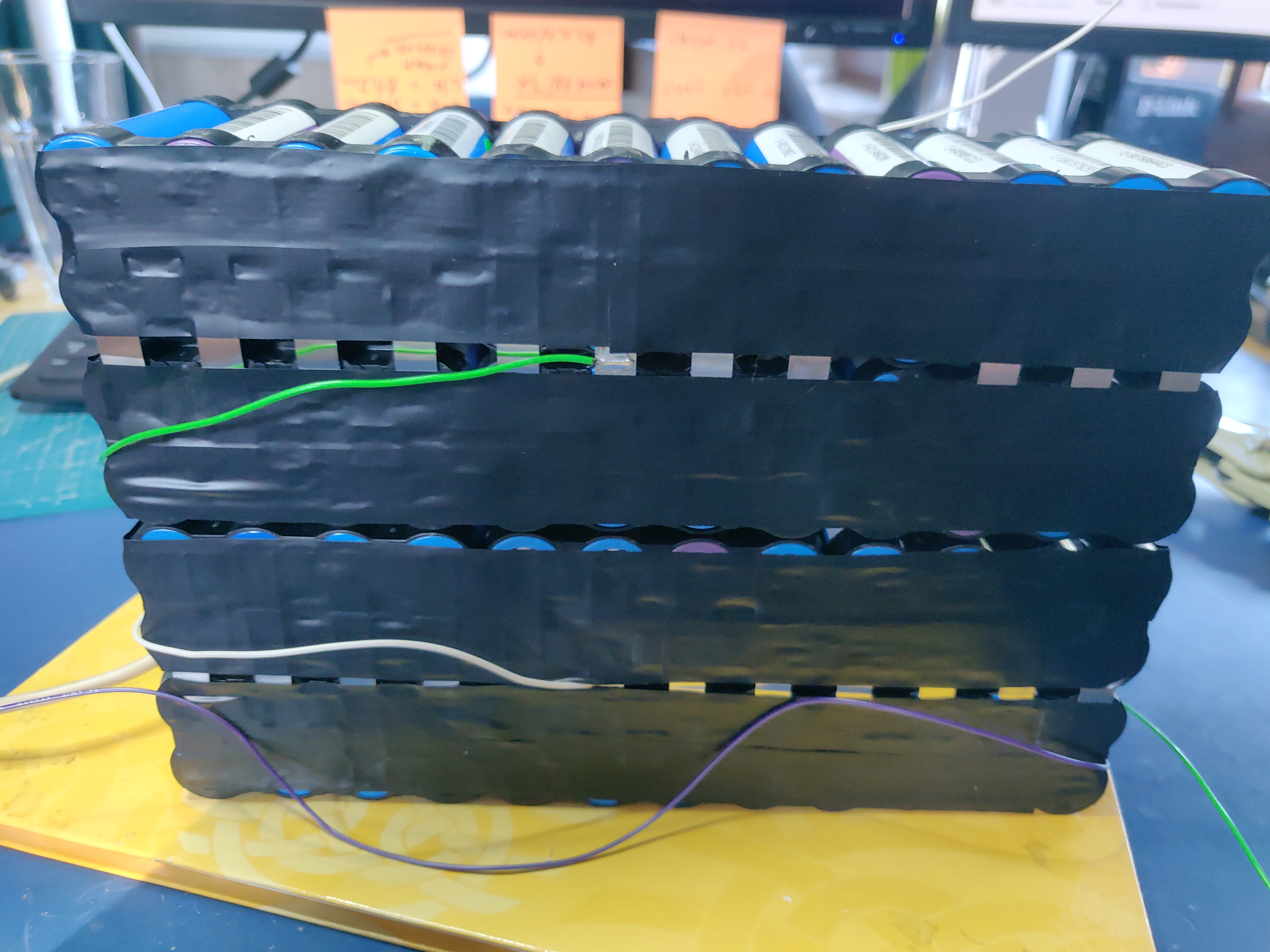
After this the pack is bent into a flat shape:
This allows the pack to be slided into the enclosure:
3.5.6. Attaching thermal fuses
During battery assembly sense wires and thermal fuses are attached. 4 thermal fuses connected in series are 60°C Normally-Connected fuses. They are attached to the battery cells using a thermally conductive glue. Magnets are used to secure the sensors as the glue takes around 24h to fully solidify.
3.5.7. Battery Management System
The BMS used with the battery pack is a EGBO Store 4S/100A based on the BM3451 made by BYD. Apart from ordinary battery protection from overvoltage, undervoltage, overcurrent, etc. it can detect the disconnection of sense wires and shut the pack down in such an instance. This feature is used to both connect thermal fuses to the battery as well as a "Battery cutoff" switch on the front panel. Both of these work by breaking the connection of one of the voltage sense wires causing the BMS to stop charging or discharging the battery.
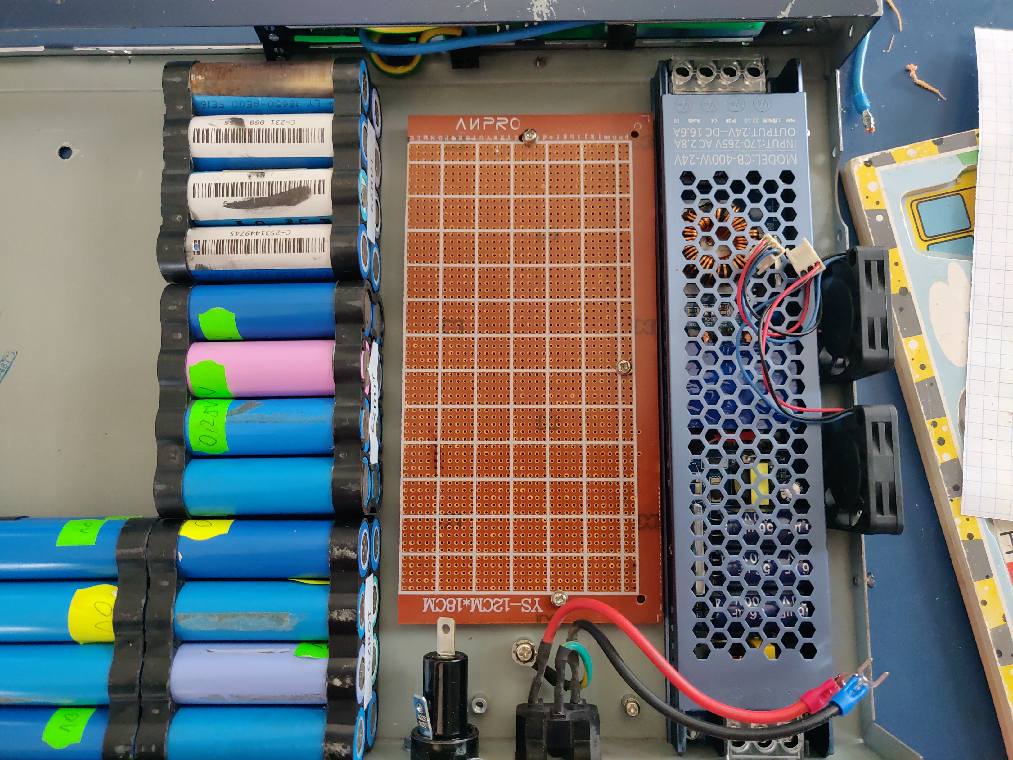
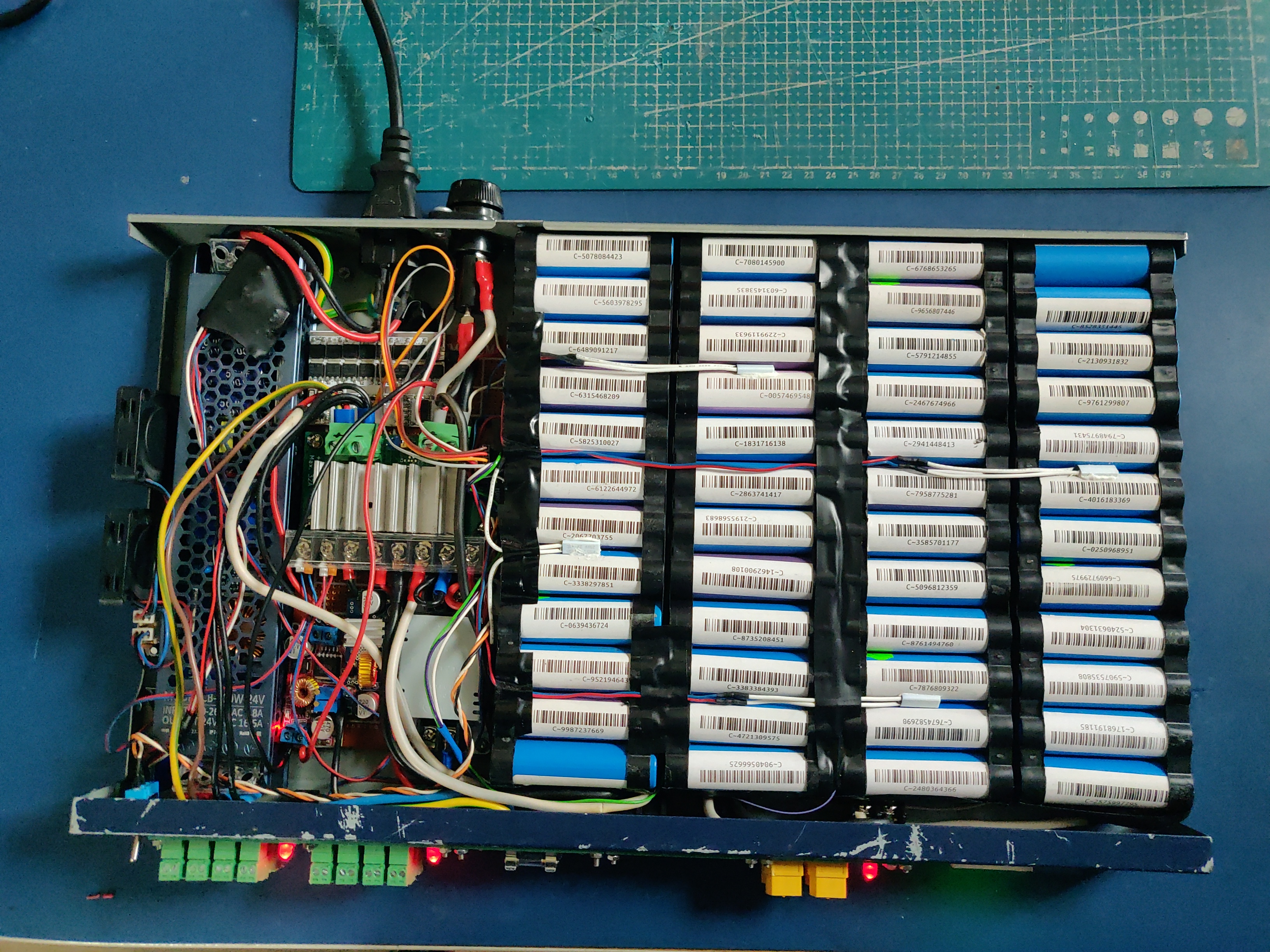
4. Final assembly photo
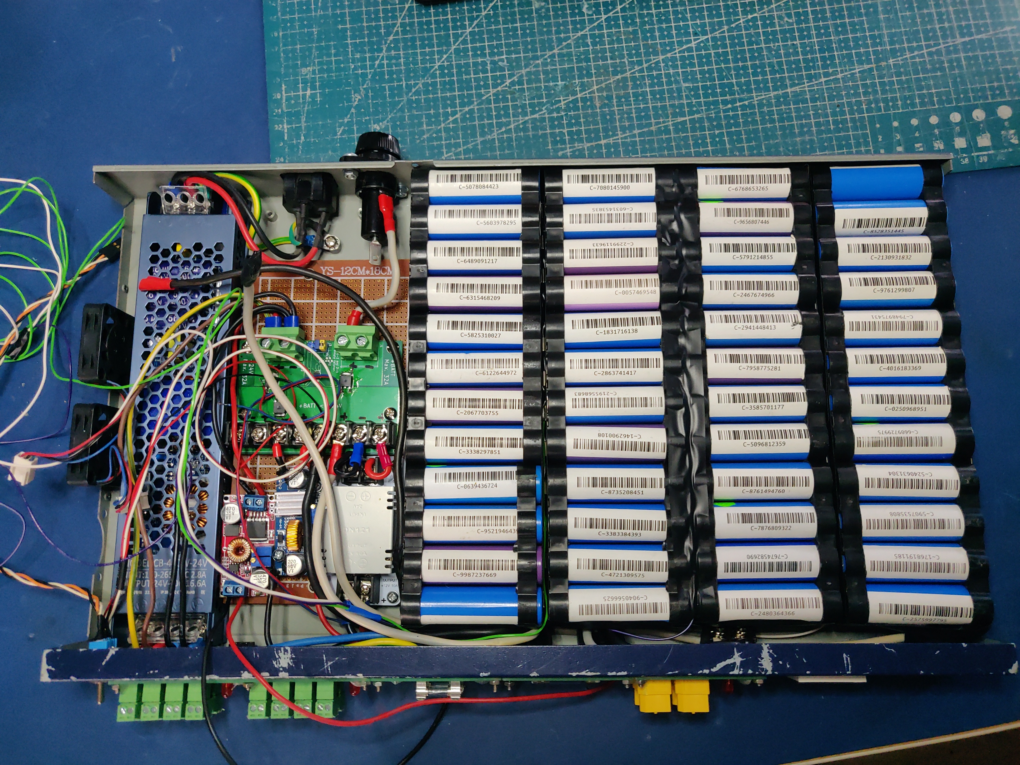
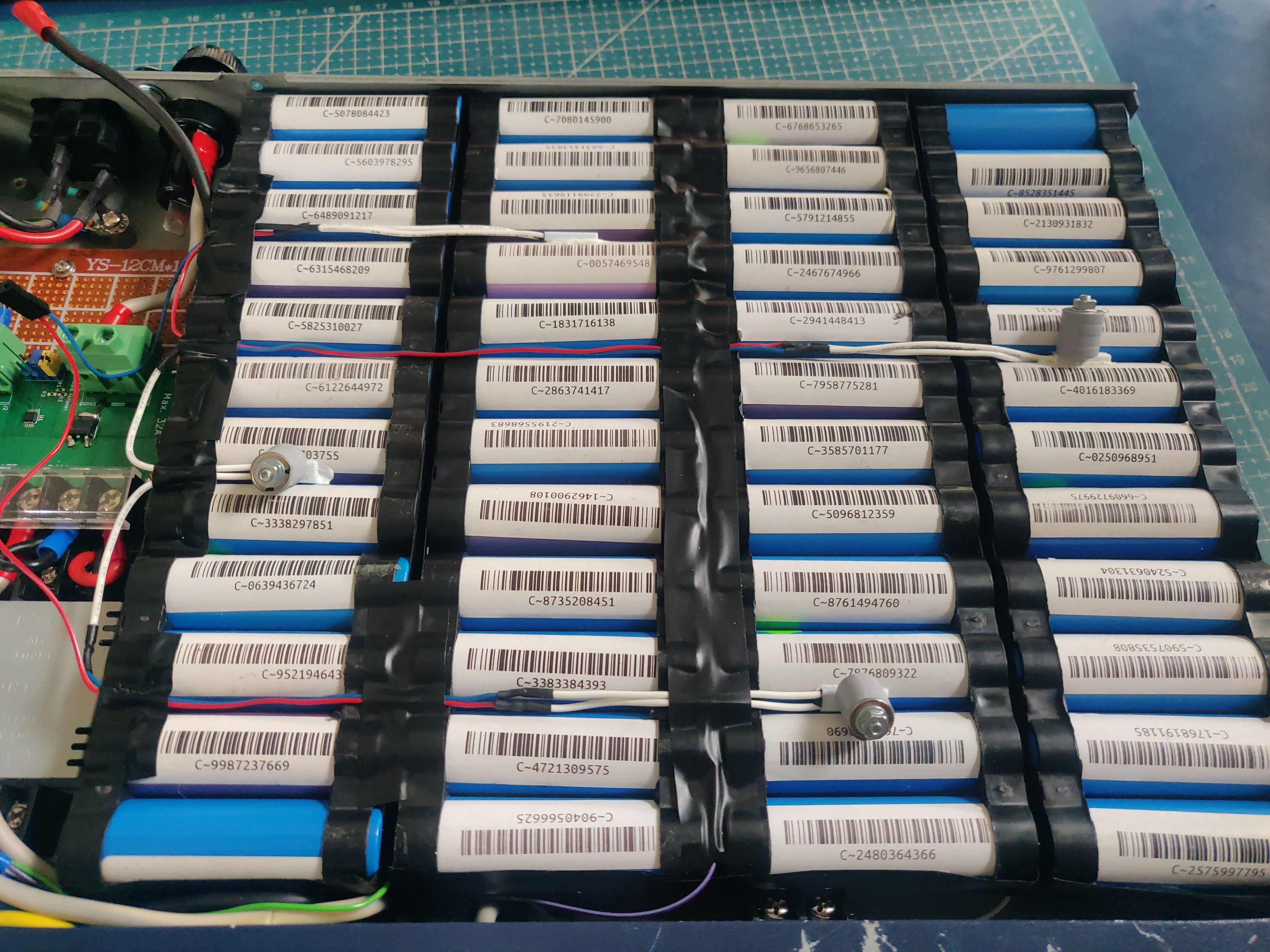
The final UPS assembled before the chassis being closed:
5. Bill of Materials
- Shipping costs and taxes are not included.
- All prices are in EUR.
| Item | Type | Description | Unit | Amount | Price per unit [EUR] | Line total [EUR] | Purchase date | Notes |
|---|---|---|---|---|---|---|---|---|
| Battery cells | Various | Li-Ion 3.6V 18650 Cells | pcs | 96 | 0 | 0 | N/A | From existing stock |
| AC Power supply | Coleen CB-400W-24V | AC 230V, 24V/16.6A | pcs | 1 | 19.9 | 19.9 | ||
| Battery fuse socket | PMG-KB-01-Q2S | Fuse holder; 10.3x38.1mm; 30A; on panel; Cutout: Ø22.4mm; UL94V-1 | pcs | 1 | 8.77 | 8.77 | ||
| Battery fuse | 0090.0030 SCHURTER | Fuse: fuse; gPV; 30A; 1kVDC; ceramic,cylindrical,industrial; ASO | pcs | 1 | 8.68 | 8.68 | ||
| 12V Buck Converter | DN121 | VOLTAGE REGULATOR 24V to 12V 10A DC/DC Converter Step Down Voltage Transformer Buck Regulator Voltage for Solar for LED | pcs | 1 | 8.62 | 8.62 | ||
| 5V Buck Converter | LM2596 Step Down Module | LM2596 Step Down Module DC to DC Adjustable Buck | pcs | 1 | 3.00 | 3. | ||
| CC/CV Charger | XL4015 | Efficient Adjustable 5A DC-DC Buck Module Constant Current Voltage Regulator Step Down Converter Charging Board 5V 12V 24V | pcs | 1 | 2.31 | 2.31 | ||
| Battery Management System | EGBO Store 4S/100A | 3s 4s 5s Bms 12v 16.8v 21v 3.7v 100a Li-ion Lmo Ternary Lithium Battery Protection Circuit Board Li-polymer Balance Charging | pcs | 1 | 2.27 | 2.27 | ||
| Pluggable terminal blocks (sockets) | 15EDGVC-3.5-02P-14-00A(H) | Pluggable terminal block; 3.5mm; ways: 2; straight; socket; male | pcs | 16 | 0.19 | 3.04 | ||
| Pluggable terminal blocks (plugs) | 15EDGK-3.5-02P-14-00AH | Pluggable terminal block; 3.5mm; ways: 2; straight; plug; female | pcs | 20 | 0.42 | 8.4 | 4 spare units | |
| Total | 67.18 |